reset/shutdown with the NESPi case reset button

got myself a NESPi case (an awesome case btw!) and after noticing that the reset button just cuts the main power i wanted a correct shutdown/restart solution.

with a bit of code, some soldering and 2 resistors it’s actually quite simple to get going.

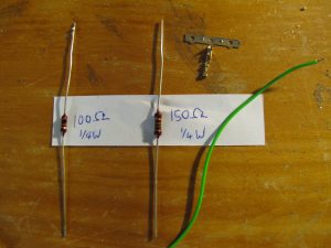
first off you need a 150 ohm ¼ watt resistor, a 100 ohm ¼ watt resistor, a bit of stranded wire and a 2.54mm female crimp jumper terminal connector (or a pi GPIO single female connector cable).

remove the top hub with the 2 usb ports and the ethernet port from the NESPi case so that you can reach the circuit with the buttons.

since the GPIO (general purpose input/output) pins on the raspberry pi can only handle 3.3 volts and the usb power on the reset button is 5V, we’ll need a simple voltage divider.

so if Vout = Vin(R2/(R1+R2)) then in our example we’d have 3V = 5V(150R/(100R+150R)) which will work great.

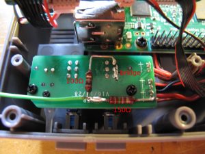
since we want the raspberry pi to always receive power even if the reset button is pressed a small bridge is needed. solder together the pins which are connected while the reset button is not pressed. check the image for more detail.
placing the two resistors in series will divide the voltage and we can use the 3 volts to pass onto a GPIO pin.

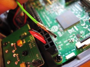
if that’s done we can hook up the jumper terminal connector to the GPIO board.
i used pin nr 5, if you change this you need to make sure your script is correct aswell.

if that’s all done let’s boot up the pi and get the scripts going.

download this script from github.

sudo mkdir /opt/scripts && sudo wget -nv -O /opt/scripts/piboot.py  https://raw.githubusercontent.com/munzli/pi/master/piboot.py

this creates and downloads to /opt/scripts/.

this script will wait for an interrupt on pin 5 and checks how long the “button” was pressed. it restarts with a short press and if held longer than 3 seconds it shuts down.

make sure you have the gpio python librarys installed

sudo apt-get -y update
sudo apt-get install --yes python-rpi.gpio python3-rpi.gpio

if you’d like to try it just call it with python (optional)

sudo python /opt/scripts/piboot.py

to get this to autostart on your pi we can use systemd.
download this file and save it to /etc/systemd/system.

sudo wget -nv -O /etc/systemd/system/piboot.service https://raw.githubusercontent.com/munzli/pi/master/piboot.service

now enable and run the service

sudo systemctl enable piboot.service
sudo systemctl start piboot.service

use systemctl to check if it’s up and running and test your reset button!

thx to ETA PRIME for the inspiration…

[edit]updated commands to fetch and save scripts, just copy/paste

bios flashing without a floppy/cd-rom/usb-stick

well i posted this in our development blog in my company and have noticed that this can be usefull for other people, but i am not responsible for anybody messing up their bios due to not knowing what they are doing!

here’s how you can flash your bios without needing a boot disk. the easy way is to use flashrom and i’ve also written a short how-to on how to boot dos from grub further below.

well installing flashrom (on ubuntu linux) is pretty unproblematic:

sudo apt-get install flashrom

just for safety create a backup of your current bios:

sudo flashrom -r bios_20101014.bin

output is something like this:

flashrom v0.9.3-r1211 on Linux 2.6.35-22-generic (i686), built with libpci 3.1.7, GCC 4.4.5, little endian
flashrom is free software, get the source code at http://www.flashrom.org
 
Calibrating delay loop... OK.
No coreboot table found.
Found chipset "Intel ICH9", enabling flash write... OK.
This chipset supports the following protocols: FWH,SPI.
Found chip "Winbond W25x80" (1024 KB, SPI) at physical address 0xfff00000.
===
Reading flash... done.

my mainboard seems to be currently untested and so i also receive this message in my output:

This flash part has status UNTESTED for operations: WRITE
The test status of this chip may have been updated in the latest development
version of flashrom. If you are running the latest development version,
please email a report to flashrom@flashrom.org if any of the above operations
work correctly for you with this flash part. Please include the flashrom output  with the additional -V option for all operations you tested (-V, -Vr,
-Vw, -VE), and mention which mainboard or programmer you tested.
Please mention your board in the subject line. Thanks for your help!

well since i’m only making a backup in this step this really is irrelevant (because i’m only reading) but i also ignored this later on and it worked perfectly.

download the bios file from the manufacturers website and then flash it:

sudo flashrom -w mynewbios.rom

here’s the output:

flashrom v0.9.3-r1211 on Linux 2.6.35-22-generic (i686), built with libpci 3.1.7, GCC 4.4.5, little endian
flashrom is free software, get the source code at http://www.flashrom.org
 
Calibrating delay loop... OK.
No coreboot table found.
Found chipset "Intel ICH9", enabling flash write... OK.
This chipset supports the following protocols: FWH,SPI.
Found chip "Winbond W25x80" (1024 KB, SPI) at physical address 0xfff00000.
===
This flash part has status UNTESTED for operations: WRITE
The test status of this chip may have been updated in the latest development
version of flashrom. If you are running the latest development version,
please email a report to flashrom@flashrom.org if any of the above operations
work correctly for you with this flash part. Please include the flashrom
output with the additional -V option for all operations you tested (-V, -Vr,
-Vw, -VE), and mention which mainboard or programmer you tested.
Please mention your board in the subject line. Thanks for your help!
Flash image seems to be a legacy BIOS. Disabling checks.
Erasing flash chip... SUCCESS.
Writing flash chip... COMPLETE.
Verifying flash... VERIFIED.

like i said i ignored the UNTESTED warning and was able to cross-flash my asus p5k-se mainboard to the asus p5kr bios (to receive ahci support for the p5k-se motherboard) without any problems.

reboot your ubuntu and set your settings in your new bios.

since i wanted ahci support i quickly checked if ahci loads properly after booting back into ubuntu linux:

lsmod | grep ahci


[alternate method]
for everybody that wants to flash using the manufacturers tool that usually only runs in DOS go for this method:

download and mount a freedos image (for example balder or freedos oem used in this example):

sudo mkdir /media/floppy
sudo mount -t vfat -o loop,quiet,umask=000 FDOEM.144 /media/floppy

now copy the bios files and your flashtool to the mounted /media/floppy (as root or with sudo).
then unmount:

sudo umount /media/floppy

move or copy the floppy image into your /boot folder

sudo mv FDOEM.144 /boot/biosupdate.img

copy memdisk to /boot (first command makes sure you have syslinux installed):

sudo apt-get install syslinux
sudo cp /usr/lib/syslinux/memdisk /boot/

now add the floppy image to your /boot/grub/menu.lst

title       bios upgrade
kernel      /boot/memdisk
initrd      /boot/biosupdate.img

then choose to boot the bios upgrade in grub while starting up (you might need to press escape to fall into the grub menu) as soon as dos is up and running use your manufacturers command in dos to flash your bios…

other methods and related topic:
http://ubuntuforums.org/showthread.php?t=318789
updating sony ericsson x10 (mini/mini pro) to android 2.1 in linux

well for all of you who like to upgrade their SE phone from a linux machine here’s a way to get it done using virtualbox… (i’m using ubuntu maverick meerkat)

first download virtualbox and install the correct version from here or for ubuntu just do a:
sudo apt-get install virtualbox-ose-qt

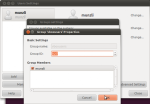
then you need to add yourself to the “vboxusers” group, this can be done using the colorful clicky menu in ubuntu by clicking System -> Administration -> Users and Groups -> Manage Groups

in older version of ubuntu and other linux distros you might need to add persmissions to usbfs for the virtualbox users. check and see if your distro has a “/proc/bus/usb” if not, ignore this next step.
edit the fstab to get the correct permission for the usb device in virtualbox

sudo gedit /etc/fstab

add this at the end (make sure you replace the XXX with the “vboxusers” group ID)

none /proc/bus/usb usbfs devgid=XXX,devmode=664 0 0

best thing to do now is a reboot ;)

so now you need to create a new virtualbox and install windows… this shouldn’t be a problem if you still have an old windows cd lying around.

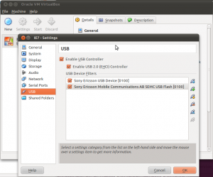
after that you need to configure that virtual machine with 2 usb filters for your phone. plug in your phone and in the virtualbox settings dialog add it to the usb filters. unplug your phone, turn it off and reboot into flash mode (hold the back key while plugin in the usb cable). now you should see a different device popup in the usb settings. add it also:

start-up your virtual machine and install pc companion or whatever and you are ready to update…

lirc and LCDproc for Soundgraph iMON changes

well… after an update quite a while ago my lirc and lcdproc stopped working. starting lirc on the default ubuntu install would always result in:

unable to load LIRC kernel modules. Verify your selected kernel modules in /etc/lirc/hardware.conf

so trying to add the modules manually would tell me a bit more:

root@augustiner:~$ modprobe lirc_imon
FATAL: Error inserting lirc_imon (/lib/modules/2.6.31-21-generic/updates/dkms/lirc_imon.ko): Unknown symbol in module, or unknown parameter (see dmesg)
root@augustiner:~$ dmesg | grep lirc_imon | tail -n1
[  420.742877] lirc_imon: Unknown parameter `islcd'

i noticed a line in the options that was wrong and removed it:

options lirc_imon islcd=0

lirc was back up and running but not my LCD screen. the logs showed:

[  492.637968] lirc_imon: lcd_write: invalid payload size: 32 (expecting 8)
[  492.762951] lirc_imon: lcd_write: invalid payload size: 32 (expecting 8)
[  492.887947] lirc_imon: lcd_write: invalid payload size: 32 (expecting 8)
[  493.012940] lirc_imon: lcd_write: invalid payload size: 32 (expecting 8)
[  493.137946] lirc_imon: lcd_write: invalid payload size: 32 (expecting 8)
[  493.262958] lirc_imon: lcd_write: invalid payload size: 32 (expecting 8)
[  493.387957] lirc_imon: lcd_write: invalid payload size: 32 (expecting 8)
...

some further googling and i found out that the options line has changed from release to release. to get it back working use:

options lirc_imon display_type=1

to get the write type just look into lirc_imon.c

enum {
   IMON_DISPLAY_TYPE_AUTO,
   IMON_DISPLAY_TYPE_VFD,
   IMON_DISPLAY_TYPE_LCD,
   IMON_DISPLAY_TYPE_NONE,
};

mythtv with mantis and DVB-S2 (TechniSat SkyStar HD2 continued…)

well thanks to awf and his comment i checked out mythtv (the release-0-21-fixes branch) and applied this patch, compiled and it kinda works.

that was the short version, here’s the longer one:

check out mythtv
svn co http://svn.mythtv.org/svn/branches/release-0-21-fixes/

download this patch right here and apply it from the mythtv folder using
patch -p0 < mythtv_multiproto.5.patch

then make sure you've got all the qt3 development libraries, the XvMC development libraries aswell as LAME and all the others (don't quite remember the whole list) but if you compile you'll find out what your missing.

to configure i used awf's parameters described in his post
./configure --enable-xvmc --enable-dvb --disable-hdhomerun --disable-firewire --enable-xvmc-opengl --enable-opengl-video --enable-opengl-vsync --enable-proc-opt --extra-cxxflags=-I/path/to/mantis/linux/include --extra-cflags=-I/path/to/mantis/linux/include
of course don't forget to correct the path to the mantis driver build.

of course now
make
sudo make install

then configure mythtv using mythtv-setup.

awf was nice enough to send me the dtv_multiplex table (which contains all the transport information for hotbird 13°E and astra 19.2°E) and so i went on to channel scanning... have all the hotbird channels... but can't scan astra eventhough i think i've got the disecq settings correct! if i look into the database it has my card and the inputs doubled, i can delete everything and it recreates them like that. soooo, a little help on the diseqc settings would be greatly appreciated ;)

of course if anybody want's the dtv_multiplex for hotbird and astra i'll gladly send it to you since it did help me out a lot! (of course if awf is cool with that)

thanks a bunch for the comments left here they helped out alot!

UPDATE: ok, got the astra channels scanned too. thanks to awf who pointed out Western union fees that i needed two video inputs (right now both set to EIT Western union fees that 's why i thought one wouldn't make a difference).

it scans ASTRA HD+ and ANIXE HD but it can't get a lock on both channels through mythtv. so the multiproto myth patch is still missing something or does anybody else have a good idea?

howto run a TechniSat Skystar HD2 on linux

since i’m switching from my analog WinTV-PVR-500 to a DVB-S setup in my mythtv box I installed a TechniSat Skystar HD2 card (a rebranded Azurewave AD SP400 CI VP-1041) and to my surprise I got it running fairly quickly.

here’s a description on the first steps i took in creating a mythtv box with DVB-S and hopefully DVB-S2.

install mercurial (distributed version control system). In debian based systems:
sudo apt-get install mercurial

then obtain the latest mantis multiproto drivers. there is no patching necessary for the card to run.
hg clone http://jusst.de/hg/mantisthen compile and install.
make
make install

more info can be obtained here under “Method 2”.

the modules can be loaded manually but to test the correct loading a reboot is easier. now the card should be loaded at boot.

to create a channels.conf you’ll need scan from the dvb-apps located on linuxtv.org.
the way to get this working quite easy is described here. the TerraTec Cinergy S2 PCI HD CI is another clone of the same card.

make sure that the changed line in the Makefile has the correct path. in the example it is
CPPFLAGS += -I/usr/src/mantis/linux/includebut since i compiled in my home directory my path was different (this is quite obvious but i thought i’d state it to be sure).

EDIT:i noticed that scan with the patch don’t work anymore… it should work just using the compiled scan in the dvb-apps/utils directory!

while running scan:
./scan dvb-s/Astra-19.2E > ~/.szap/channels.confcheck to see if these lines (or any stating: Using ‘STB0899 Multistandard’ DVB-S2) appear.
----------------------------------> Using 'STB0899 Multistandard' DVB-S2
Tune to frequency 11914500
DVB-S IF freq is 1314500
0x0006 0x0081: pmt_pid 0x0062 PREMIERE -- PREMIERE HD (running, scrambled)
0x0006 0x0082: pmt_pid 0x0063 PREMIERE -- DISCOVERY HD (running, scrambled)
0x0006 0x0084: pmt_pid 0x0065 BetaDigital -- ANIXE HD (running)
0x0006 0x0083: pmt_pid 0x0064 BetaDigital -- ASTRA HD+ (running)
then you know that DVB-S2 is working also! yay!

afterwards i had 1187 services only on Astra 19.2E. half of them scrambled but hey, the numbers count ;)

now to test the whole thing enter the dvb-apps/test directory and try zapping to a channel (check in the ~/.szap/channels.conf to see which number is good to go and not scrambled).
./szap2 -r -n 085
the output will show you some channel data and as soon as “FE_HAS_LOCK” is displayed (keep szap running) open mplayer in a different terminal
mplayer /dev/dvb/adapter0/dvr0
and you should see a picture! alright, the card is up and running!

all seems good but i still have a problem with DVB-S2. and that is as soon as i’m trying to display a DVB-S2 channel like ANIXE HD (channel #550 in my channels.conf)
./szap2 -r -t 2 -n 550i get a “FE_HAS_LOCK” but mplayer then just returns:
TS file format detected.
VIDEO MPEG2(pid=1535) AUDIO A52(pid=1539) NO SUBS (yet)! PROGRAM N. 0

and that’s it…

i think i’m missing some codecs or something (w32codecs,DeCSS, x264, etc. is installed).
any help is appreciated though ;)

NOTE: don’t forget to add the option “-t 2” for DVB-S2 for szap

UPDATE: i noticed that when i zap to a HD station and wait long enough i get this error right after the “TS file format detected”:
Too many audio packets in the buffer: (4096 in 7340032 bytes).
Maybe you are playing a non-interleaved stream/file or the codec failed?
For AVI files, try to force non-interleaved mode with the -ni option.
MPEG: FATAL: EOF while searching for sequence header.
Video: Cannot read properties.

so i’m still unsuccessful at watching HD tv.

UPDATE 2!!: to watch HD tv stations you need the option -p when calling szap2!
-p : add pat and pmt to TS recording (implies -r)

so try
./szap2 -r -p -t 2 "ASTRA HD+" and open mplayer… wow

my 3GHz system that’s gonna be the mythbackend sometimes quits with mplayer saying:
************************************************
**** Your system is too SLOW to play this! ****
************************************************
which means… my frontend system is gonna have to be upgraded!

canon powershot G7

i recently bought myself a Canon Powershot G7 and i’m really pleased with it. great camera with the retro looks of an old analog cam.

it handles macro shots really good, i was playing around with it for hours and made a bunch of nice pics which i posted in this gallery.

i also bought the WP-DC11 marine kit.
wp-dc11
which is loads of fun. we tested it at a friends pool party and made tons of fun pictures (this example doesn’t have the best colors but you get the point)
underwater sample

for anybody that doesn’t want to buy a single-lens reflex (SLR) camera this is one that gets pretty damn close to it!

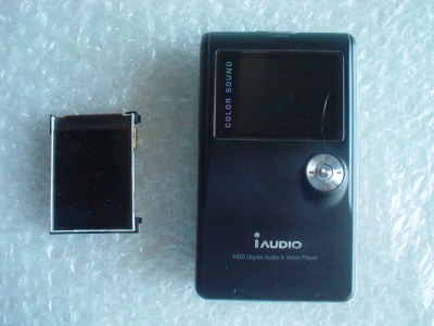
replacing the display of your iAudio X5

well i ruined my display and finally was able to get a new one.

the X5

since i thought it was no biggie to replace myself i started disassembling my X5.

step 1

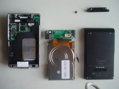
after opening the next step was removing the hard drive.

step 2

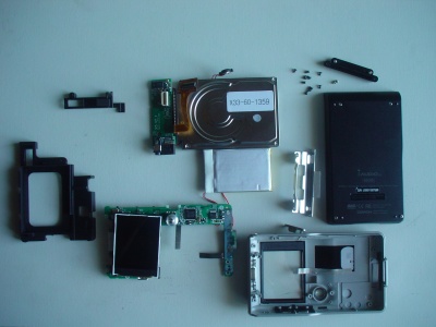
i had to complety remove everything to reach the display.

disassembled X5

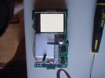
the replacement display in place i put it together to check if it worked. i wasn’t carefull enough so i had to solder the battery cable back on, because i accidentally tore it off (so be careful if you plan on doing something like this too).

and when i turned on the device the backlight seemed to work but my display didn’t. :(

testing the display

looks like i’m gonna have to send it in for repair anyway since the display controller seems to be broken too. always fun to look into electronic devices though ;)